A) Generating set control module HGM6120CAN features:
Configurable via PC software or the front panel
5 programmable inputs (configurable for digital or analog signals)
4 programmable relay outputs
Monitors 3-phase generator and mains (utility) voltage
Event log (50 records)
Configurable timers and alarm protection thresholds
Automatic shutdown or alarm upon fault detection
Supports remote start/stop and load transfer
Engine pre-heat control (relay output)
Precision measurement and display of engine and electrical parameters
Engine total run time accumulation
Red LED indicators for alarms/shutdown
LCD display with backlight, supports 8 language interfaces
Front panel test button
Modular design, flush mounting
B) Metering via LCD display:
Generator Voltage (L-L / L-N)
Generator Current (L1, L2, L3)
Generator Frequency (Hz)
Generator Power (Kw)
Generator Power Factor (COS Φ)
Accumulated Generator Energy (kWh)
Load Percentage (%)
Engine Oil Pressure (kPa / psi / bar)
Engine Temperature (°C / °F)
Fuel Level (%)
Battery Voltage (V)
Charger Voltage (V)
Mains Voltage (L-L / L-N)
C) Alarms:
Under Speed / Over Speed
Under Voltage / Over Voltage
Under Frequency / Over Frequency
Overload / Over Current / Overpower
Low Engine Oil Pressure
High Engine Coolant Temperature
Low Fuel Level (Optional)
Low / High Battery Voltage
Emergency Stop
Charge Fail
Sensor Open Circuit
Fail to Start
ECU Communication Failure (for EFI engines)
Maintenance Due
Aftertreatment System Related Alarms (foraftertreatment EFI gensets)
2. Power Outlet Terminal Board Mounted on the Gen-set Base Frame
Tab 4
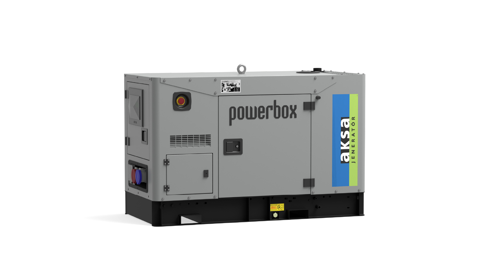
Canopy
ACP 1A-PB
Steel structures.
Emergency stop push button.
Control panel
Corrosion-resistant locks and hinges.
oil could be drained via valve and a hose
Exhaust system in the canopy.
special large access doors for easy maintanance
Base frame -fuel tank.
Lifting Points.
sound proofing materials
Power out
Introductıon
Sound-attenuated and weather protective enclosures for generating sets from Aksa, meet event the sound requirements and provide optimum protection from inclement weather and development by our specialist acoustic engineers. Our modular designed sound insulated canopies (8 – 275kVA) fit directly to the open generator set to provide ease of access for servicing and general maintenance and interchangeable components permitting on-site repair. Enclosures are designed to optimize genset cooling performance, providing you with confidence that genset ratings and ambient capability.
General Characteristics
Compact footprint, low profile design.
Enclosure, generator set, exhaust system and base-tank are pre-assembled, pre-integrated and shipped as one package
Body made from steel components treated with polyester powder coating
Fire retardant foam insulation
Easy access to all service points
Exhaust system inside canopy
Large doors on each side
Control panel viewing window in a lockable access door
Emergency stop push button mounted on enclosure exterior
Cooling fan and battery charging alternator fully guarded
Fuel fill and battery can only be reached via lockable access doors.
Lifting points on the top of canopy and base frame
Customer options available to meet your applications needs.
Length (mm)
1672
Width (mm)
823
Height (mm)
1127
Fuel Tank Capacity (l)
32
Tab 5
Open Group
Cabin Group
Tab 1
*Images are for illustrative purposes only; actual presentation may vary.

 Engine Specifications
 Alternator Features
 Control Panel Features
 Cabin Features
 Dimensions and Weights


 Transfer Board
 Auxiliary Equipment